IndiaSoft Technologies (P) Ltd.
DUA Building, 2nd Floor, Ghule Patil Road, Near Raheja Vista Premiere, Mohammedwadi, Pune – 411060.
Ph. : +91 9325111066, E-mail: rkirani@indiasoft.co.in, mail@indiasoft.co.in, www.indiasoft.co.in
Powerful & Intuitive Modeling, Simulation & Optimization Tools
Engineering Simulation Solutions

Robotics: Industrial Robotic cells with Experiments & Simulation Software
-
Fanuc 6 Axes Robot Cell with multiple Experiments & Vision Inspection
-
Dedicated Robotic Welding Cell
-
Industrial 10Kg Payload Robot with 10 Experiments, Open-Source Controller
-
SCARA Cell with Experiments
-
Advanced Multiple brands & models Robotics OLP, Simulation, 3D Factory Simulation, Throughput calculations, PLC connectivity & more using VISUAL COMPONENTS.
Industrial Robotic Cell, 10 KG Payload, Open Source Controller, 10 Industry Applications


-
10KG PAYLOAD
-
750MM LARGE WORKING ENVELOPE
-
USER-FRIENDLY INTERFACE
-
OPEN-SOURCE
-
INBUILT ARDUINO AND RASPBERRY PI
-
INBUILT PLC
-
PLUG AND PLAY DESIGN
-
Open Architecture for Robotics Learning
Salient Features:
-
Allows access to the controller for open platform learning and development.
-
Programming flexibility with native language, Ladder Diagram (LD), Instruction List (IL), Function Block Diagram (FBD), Structured Text (ST), and Sequential Function Chart (SFC).
-
Future ready, incorporating IEC's IEC61131-3 global standard for programmable controllers.
-
Compatibility with LabVIEW, MATLAB, Visual Studio, and Java.
10 No’s Ready Industry Applications with Work Table:
-
Voice command: Android based Application suitable to All Android Mobile. User friendly Interface for better clutter free experience.
-
Colour sensing: Open source vision sensor for universal Integration and standalone microcontroller for various applications
-
Industrial spraying: Learn to use the robot for spray coating tasks, enhancing uniformity and reducing waste
-
Material sensing: Use the robot to sort items based on their material composition, crucial in material-specific production lines
-
Palletising: Utilize the robot for stacking and arranging products systematically on a pallet, increasing speed and efficiency in packaging
-
Vacuum gripping: Use vacuum power to grip and handle objects, a versatile method for material handling
-
2D Path following: Program the robot to follow specified 2D paths for tasks such as cutting or drawing
-
Magnetic pick and place: Use the robot with electromagnetic gripping technology to move ferrous items efficiently
-
Glueing: Applying various adhesives on parts such as engine heads, gaskets, mirrors etc. using robot
-
Spot welding: The package includes a 100 Amp Spot Welding Power Source, a versatile Application Table, a precision Spot Welding Gun, and assorted Spot Welding Fixtures for diverse project needs.


FANUC Robotic Cell with Experiments

Industry Grade ROBOT Cell, 6 Axes
Robocell is a complete cell for training on pick and place robot. Equipped with Fanuc robot, Robocell is designed to provide hands on experience all real time applications of handling robot.
The basic concept of this Robocell is to provide training on not only robot operation but also on the interface of robot with peripheral automation components. Participants are expected to operate the robot in individual mode as well as in AUTO mode in collaboration with other automation components such as three jaw chuck, machine vice, press assembly and vision sensor.
The Robocell is provided with castor wheels with mounting arrangement. All four sides of the cell are enclosed with acrylic doors and windows for maximum visibility to participants. Three story tower lamp with buzzer mounted on the top indicates the present status of the Robocell. Basic instructions for robot operations are clearly mentioned on the Robocell .
The cell is provided with Teach pendant for robot programming and an operational remote for robot operation in AUTO mode.
Teach Pendant is provided for teaching of the robot. Operational remote is provided for robot operation in Auto mode.
Accessories such as AUTO mode indicator, three story lamp with buzzer, FRL for pneumatic air supply, Mains ON Indicator, Battery alarm indicator are also provided on Robocell.
Experiment table 1 is a Pick and Place Table which can be used for basic robot teaching exercises along with palletizing operations.
Experiment table 2 is an assembly table which is equipped with pneumatic press application along with slide cylinders. Participants can carry out the assembly application of bearing and shaft in complete automation directly from robot programming through teach pendant.
Experiment table 3 is a machine tending table equipped with pneumatic chuck and pneumatic vice.
Experiment table 4 is a vision sensing table with necessary lighting arrangements.

4 axes Industrial SCARA Robot training System

Job is placed via a dispenser on to a load cell. The measured weight of the job is displayed on a digital display. Analog output is also provided from an amplifier which can be used to display the weight in SCADA. Depending on the weight of the job, user can decide to store the job in a particular slot in the pallet (total 9 slots are available)
Participants are expected to have hands on experience on Cell programming through which they can decide the flow. 4 axes industrial SCARA robot is used to transfer jobs from conveyor to the SCARA pallet. Industrial teach pendant is provided for SCARA operation as well as programming. Software with 3D simulation of SCARA for designing as well as executing various individual SCARA programs is also provided along with the system.
4 Axes Industrial SCARA Training cell:
• Make: Mitsubishi Model: RH-3CH (Or Equivalent)
• Payload Capacity: 3 Kg.
• Reach: 400 mm
The SCARA Cell consists of the following Features:
• Conveyor (70 x 500mm) Module
• Weighing Module
• Rotary Pick and Place Unit
• Rotary Rejection Module
• SCARA Robot
• Job Stacker
• Air Treatment Unit
• Operation control
• PLC Control Unit
• HMI Control Unit
• Valve Bank
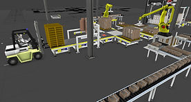
Visual Components for Advanced Multiple brands & models Robotics OLP, Simulation, 3D Factory Simulation, Throughput calculations, PLC connectivity & more.


-
Drag and Drop 3D machines, Robots and components and model a complete Manufacturing Automation System / Factory. Simulate the entire System in 3D.
-
Contains over 2,700 pre-defined and ready-to-use components, such as CNC Lathe, CNC Mill, CNC Grinding, Part Feeders, Configurable ASRS, various types and brands of Industrial Robots, Conveyors, Gantry, AGV, Shuttle Conveyor Gantry and many more.
-
We can define process, production workflows and generate throughput charts in form of Line, Bar, Area or Pie Charts.
-
You can build your own Computer Integrated and Flexible Manufacturing Systems (CIM & FMS).
-
You can configure and program ASRS (Automatic Storage and Retrieval Systems) as well as AGV (Automated Guided Vehicles).
-
Basic Robot Programming: 100’s of Robots available, you can program the robots in a virtual environment using offline robot programming (OLP) tools.
-
Robots from various market leading manufacturers such as ABB, KUKA, YASKAWA, FANUC etc. are readily available to be programmed with a mouse click. Each axis of all these various robots can be simulated.
-
We can Import 3D CAD files and create our own machines and mechanisms for use in Simulation model.
-
PLC Connectivity: Connects to various PLC brands through OPC UA interface. Also has its own PLC Ladder software for Siemens S7 PLC.
-
You can dynamically collaborate with any PLC for Hardware control and can connect to existing FMS.
-
2000+ Ready to use parametric models using which students can build variety of virtual factory setups.
-
Provision to measure various KPI (Key Performance Indicators)
-
Provision to connect to various Cloud and IIoT platforms
-
Provision to export the files into VR (Virtual Reality) format, which enables a virtual tour of the simulated factory using your mobile phone or VR glasses.


Features of Visual Components:
-
LAYOUT CONFIGURATION: Configure layouts using our simple, component based system. Use your own custom components and CAD models, or our free e Catalog, which includes 2,300+ pre-built simulation ready components.
-
PROCESS MODELING: Define and manage the products, processes and process flows in your layouts with simple, easy and visual workflows.
-
CAD COMPATIBILITY: Import CAD models directly into the Visual Components 3D world. Most major file formats and extensions are supported.
-
PROJECT READY DELIVERABLES: Export presentation-ready content with 1-click: 4K videos, 3D PDFs, 2D drawings, pictures and experience your simulation in VR and mobile.
-
SIMPLE ROBOTICS: Define, model, and simulate robotic behaviour and actions. Perform analyses such as reachability and collision detection.
-
PLC CONNECTIVITY: Connect simulations with your control system using OPC UA or supported vendor specific interfaces.
-
STATISTICS AND REPORTING: Create custom charts, graphs, and dashboards to visualize simulation statistics. Export data in supported formats.
-
COMPONENT MODELING: Bring your CAD files to life and customize them with behaviours and properties to build your own personalized library of components.
-
WIZARDS: Activate CAD files for the 3D world faster with wizards that automate configuration for many component types.
-
BASIC CAD: Create simple 3D geometries and modify imported CAD files with this basic CAD modelling toolkit.
-
GEOMETRY SIMPLIFICATION: Reduce file sizes and improve simulation performance with the automated geometry simplification tool.
-
VRC CONNECTIVITY FOR UR AND STÄUBLI: Supports connectivity to Universal Robots and Stäubli CS8 controllers.
-
VIRTUAL TOPOLOGY: Provides well-structured data of geometry surfaces, curves, and curve loops from imported CAD files. Use the topology API to develop custom robot path planning and teaching tools.
-
CURVE TEACHING TOOL: Automates robot path planning by analysing object geometries, making paths predictions, and suggesting robot paths.
-
INTERACTIVE VR: It’s possible to create a streaming connection to Visual Components Experience, allowing users to interact with the VR environment.